 |
||
|
Intelligent Power Management 
Introduction Axiomtek has committed to providing reliable power protection solutions for its industrial PC products, which are deployed in mission critical environments for applications such as on-board mass transit surveillance, factory automation or rugged outdoor applications where highly reliable computers are the key to the continuity of operations. In many industrial processes, the continuity of power supply is required 24/7. The power source needs to be regulated and protected to prevent loss of important information or costly downtime, for example in a production line environment. The computers used to control the operations should be ready to predict and respond quickly to a sudden power failure. Many of Axiomtek’s embedded motherboards and systems offer the IPM feature to combat power fluctuation issues. The Intelligent Power Management (IPM) functionality is integrated into the CPU motherboard or offered as a separate module. In this article, the focus will be on the general hardware structure and functionality of the IPM unit utilized in transportation embedded systems designed by Axiomtek. We will also showcase the ease of use of the system’s utilities, e.g. setting changes through the BIOS or OS. Intelligent Power Management of Axiomtek’s tBOX Products One example of Axiomtek products that contain the IPM module is the tBOX324-894-FL. The module is designed to handle a 9 - 36V wide range power input while ensuring that it delivers a stable and safe 12V power supply to the CPU motherboard. The Axiomtek IPM’s power input includes an additional Accessories/Ignition ACC input pin, a standard power switch pin used in various transportation applications.
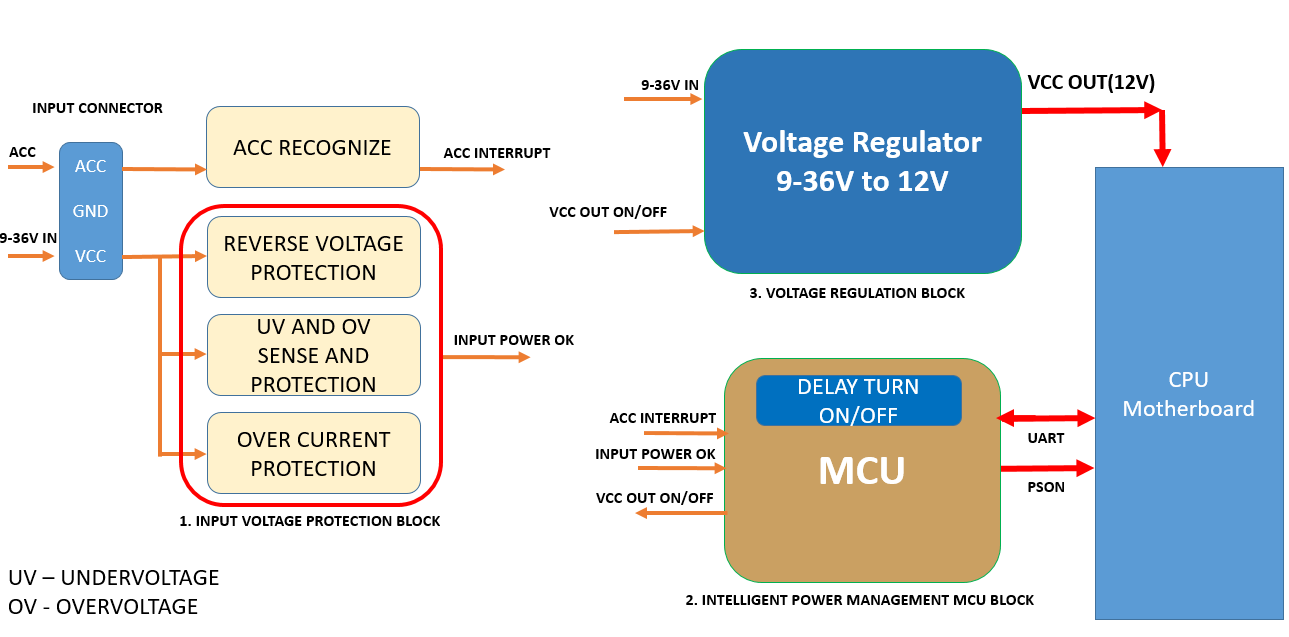
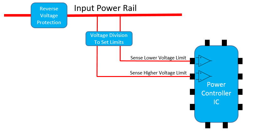
Figure 1 Its ability to control the voltage and deliver stable 12V power can be explained by means of 3 main operational blocks. 1. Input Voltage Protection Block In industrial applications where the power supply voltage is not stable or is provided by a battery, it is important for the controller to be able to operate with a wider range of voltage inputs than the conventional, fixed 12V or 24V DC. In most transportation applications, the main source of power is the battery. When a battery discharges over time, the voltage level starts degrading. At some point, it will no longer be able to power the system. It is therefore important to detect the instability of the voltage and predict the pace of battery drainage. With the IPM, an alert system is put in place to prevent operational failure due to power instability issues. The controller can predict the inevitable shut down of the system. Subsequently, it can take loss prevention steps such as securely saving important data and information created by all running programs, closing the programs and eventually shutting down the system safely. A. Reverse Voltage Protection Reverse voltage is a common concern for industrial applications. In many instances, the input power can be delivered without the standard power connectors through bare wires reworked to fit into a Phoenix-type terminal connector. In such a configuration, the probability of confusing or mixing the polarity of the power input is high, resulting in major damage to the system and rendering it useless in a matter of seconds. B. Under-Voltage and Over-Voltage Protection Under- and over-voltage protection is accomplished by setting limits, sensing the upper and lower limit settings, and feeding the information to the power protection controller chip for any required action. See Figure 2 below for a block diagram of how the Power Controller IC receives information about the input voltage.
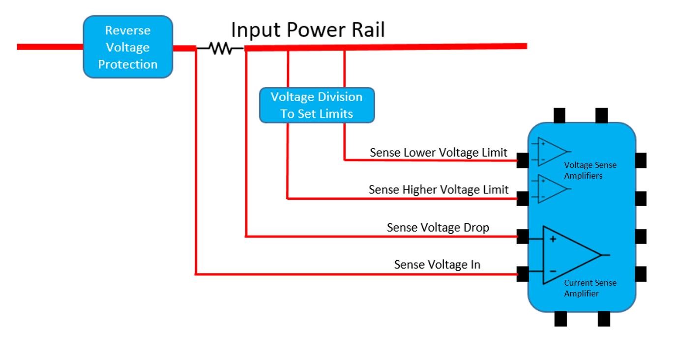
Figure 2 For example, the limit for low voltage is set to 9V while the high voltage limit is set to 36V. The voltage is fed into one of the inputs of the IC that controls the under-voltage level. If the feedback voltage detected is lower than a certain reference voltage level inside the IC (for example 1.25V), then the output of the power protection IC will be switched off. The over-voltage protection works the same way. For example, if the feedback voltage is higher than 1.25V, the output voltage of the controller circuit will turn off or not turn on. C. Over-Current Protection Over-current protection is achieved by placing a low value resistor (in the milli Ohms range) in series between the load and input voltage. Both ends of the resistor Rsense are inputs to the current sensing amplifier (see Figure 3 below). If the current through the resistor increases the voltage level beyond the set voltage drop and the Voltage In, or if it reaches the maximum defined limit set by the controller chip – e.g. 50mV, the IC will shut off the power supply to the system. The amount of current allowed to pass is dependent on the resistor value. If the resistor value is 1 milliOhm and the maximum voltage of the amplifier input is 50mV, then the allowed current will be 50mV/1milliOhm = 50A. The current limit can be reduced by adjusting the sensing resistor. For example, if the desired current limit is 10A, then the sensing resistor value must be changed to 5mOhm: 50mV/5milliOhm = 10A.
Figure 3 2. MCU Block The MCU block acts as the brain of the IPM module. It receives signals from different blocks that can indicate that certain actions have taken place. It can also send signals that will have specific meanings for the receiving blocks. 3. Voltage Regulation Block The Voltage Regulation Block is used to maintain a stable voltage level and is one of the more complex blocks designed to deliver an optimum level of low-noise, stable and fixed output voltage. The main purpose of the Voltage Regulation Block is to provide fixed voltage output, e.g., 12V, when the input voltage varies from 9 - 36V. There are several topologies including Buck, Boost, Buck-Boost, isolated and non-isolated topologies. Designing each voltage regulation circuit topology requires different approaches. The process begins with a schematic design that includes thermal considerations of heat dissipation, especially in high current and high power systems.
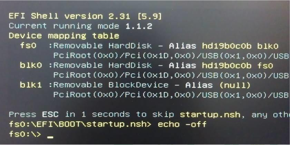
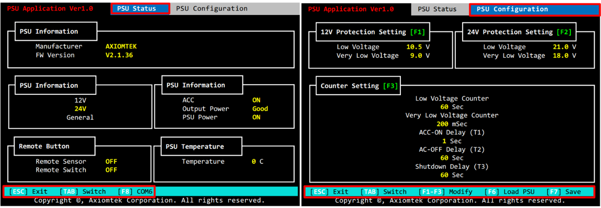
Figure 4 Next, in the power management settings, all of the important information regarding the power supply status can be found as seen below:
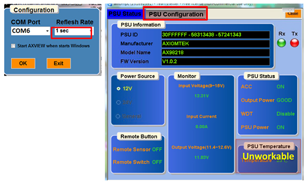
Figure 5 Use Tab to navigate through both pages. In the PSU Configuration, some modifications can be made to parameters such as voltage levels and delay times, etc.
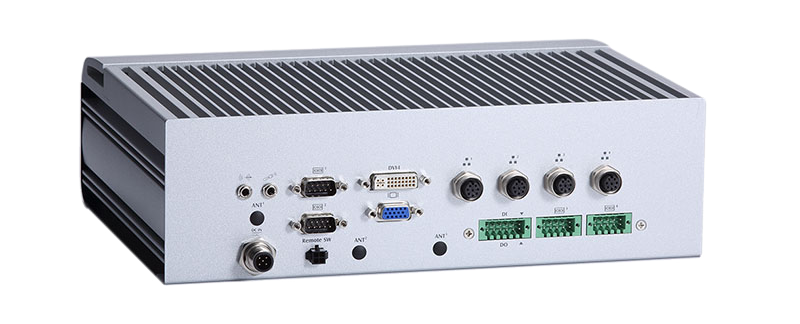
Figure 6 ACC INTERRUPT – Transportation Systems The abbreviation ACC comes from the word “Accessories” and was first introduced in cars as one of the positions on the ignition switch. When a car key is inserted into an ignition switch and turned to the left, the ACC circuit is turned on. This allows you to have the power supply to operate the radio, the windows and other accessories. Nevertheless, it does not turn on the vehicle’s fuel pump and other engine controls. The battery power is saved for use when the vehicle is started. For commercial vehicles, there is a set list of peripheral circuits that use battery power in the ACC mode. In other industrial transportation fields, the number of related applications can be higher than those of commercial vehicles. Additional computers may be required to control the additional devices, e.g. cameras, bill scanning devices, sensors for door opening and closing, etc. Axiomtek tBOX Power Connector The tBox products include the ACC pin at the power input that acts as the power ON/OFF switch. For example, in the tBOX324-894-FL the photo below shows the green Phoenix type connector at the bottom left. It is the main power input. The tBOX324-894-FL can accept a range of voltage inputs of 9 - 36V. Pin + is connected to voltages between 9 and 36V 1. ACC Turns ON – Once the ACC is ON, ACC recognition circuitry sends the signal to the Power Management MCU Block. After a specified delay, it will turn the computer ON automatically. Applications Axiomtek offers many high quality transportation-certified solutions that have the Intelligent Power Management feature. Below are two examples of applications for which the feature helps provide operational stability in mission critical environments. |
||
| www.axiomtek.com |
Copyright 2020 Axiomtek Co., Ltd. All Rights Reserved
|
|
